Infrared Gap Counter
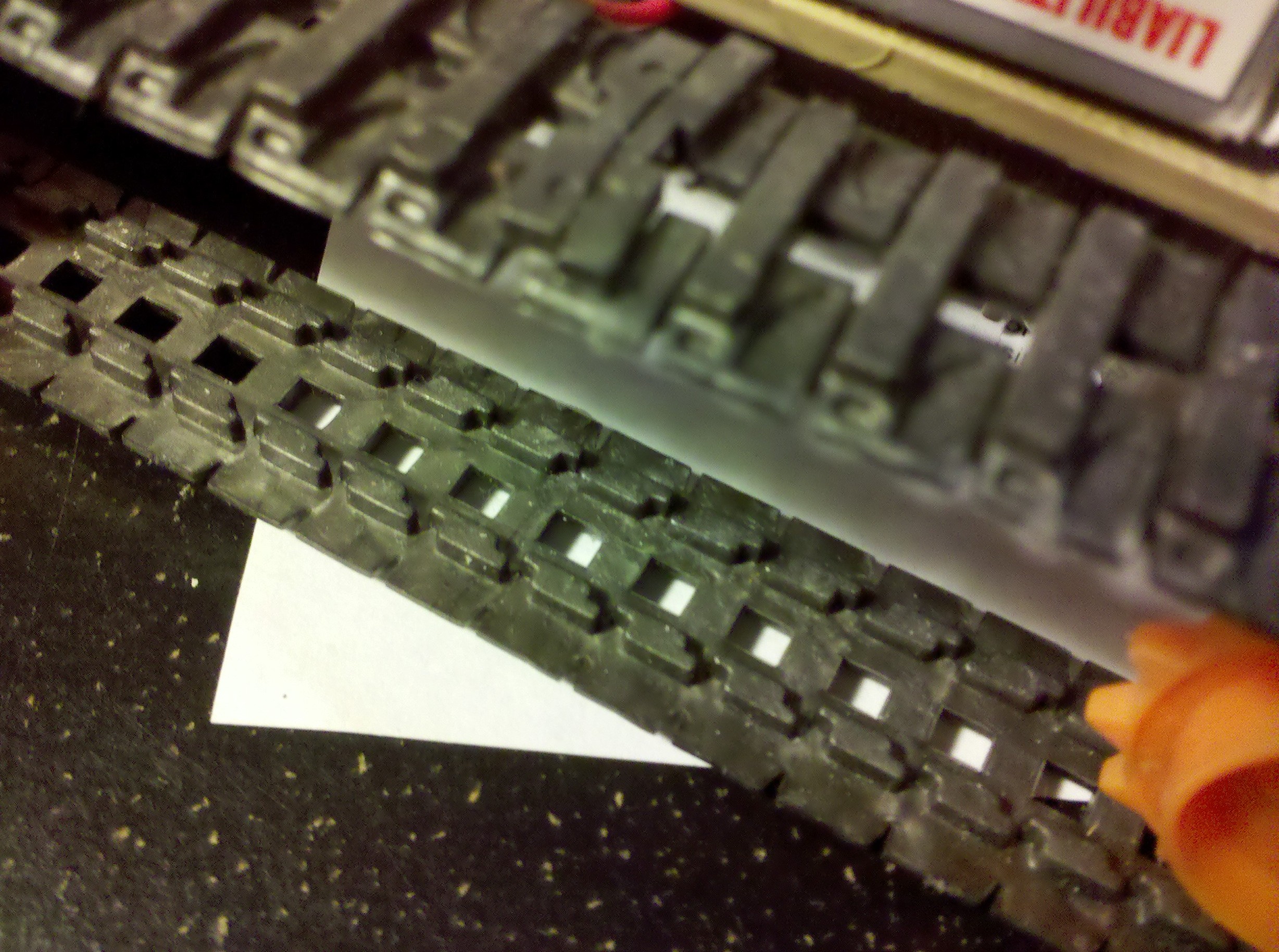
 I wanted to enable my robot with a sense of distance. Luckily my robot has build in distance markers in its tank treads. There are little gaps in the treads which I can put infrared emitters and detectors on either side of. This will allow my arduino to count the number of gaps that have passed by while the robot is moving.
The number of gaps is a constant and so I will be able to count the number of revolutions of the track and measure the distance that the robot has traveled. Furthermore, by putting a gap counter (an emitter and a detector) on both the right and left tracks I will be able to calculate the angle that the robot has turned when it does so.
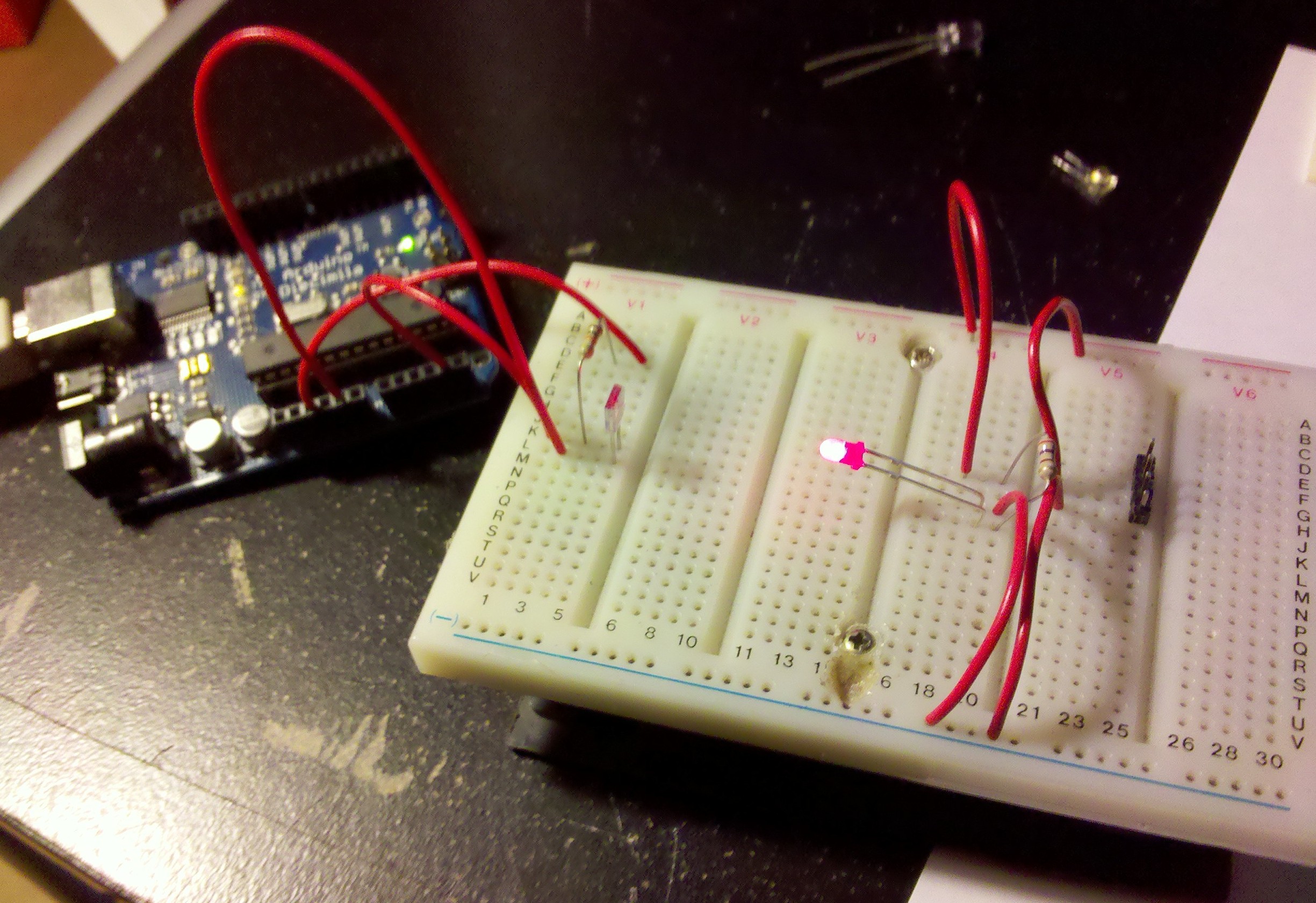
I’ve developed a proof of concept and tested it with a piece of track that I had leftover.
 The electronics are pretty simple. The infrared emitter is simply an LED that emits infrared light instead of visible light. In my concept, I used a regular red LED because the detector was just as able to pick up on that as it was on the infrared LED (and because I am a little short on infrared LEDs).
The infrared detector works like a transistor except instead of using a base to trigger the flow of electrons from the collector to the emitter it uses infrared light. So when you shine infrared light (or a red LED in my case) on the detector it allows electricity to flow from the collector to the emitter. Pretty simple.
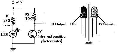
 Here’s the schematic for the circuit that I used. Again, when there is infrared light shining on the detector (Q1), it allows electricity to flow from the collector (no arrow) to the emitter (arrow). When electricity is flowing through the detector, the electrons do not want to go to the output since there is greater resistance there, so most of them go through the detector. When you block the infrared light from getting to the detector, the detector doesn’t allow electricity to flow through it and so most of the electrons go through the output. I tied the output to an analog input on my arduino (pin 4) so that I would be able to tell if the infrared light was being blocked or not. A higher reading (voltage level) on pin 4 would mean there is no infrared light shining on the detector, and a lower reading on pin 4 would mean that there is light shining on the detector.
Now that you understand that (assuming that made any sense to you), the rest is pretty simple. Below is the arduino code for my proof of concept. Essentially it increments a counter every time it senses a gap. When it senses a gap it waits until the gap is over to start looking for another one.
int sensorPin = 4;
int counter = 0;

void setup() {
  Serial.begin(9600);
}

void loop() {
  int sensorValue = analogRead(sensorPin);
  if (sensorValue < 400) {     //if there is a gap
     counter++;                //increment the counter
     Serial.print("counter : ");
     Serial.println(counter);
     boolean low = true;
     while (low) {   //wait until the end of the gap to reset
       sensorValue = analogRead(sensorPin);
       if (sensorValue > 400) {
         low = false;
      }
    }
  }
}
Here is a video of this idea in action. I’ve set up a gap counter on the tank treads so that I can measure the distance that the robot has traveled. The code I have running rotates the tank tread until 50 gaps have gone by (all the way around). I’ve marked the starting point with a white dot. It’s a little hard to see but you get the idea.